Close this alert
Crawford Cdm9 950 Installation Manual Top -
The CDM9 950 features a manual release mechanism (either a rapid release cord or a hand crank/chain) for power outages. Route the release cable away from moving parts.
(Related search suggestions provided.)
Many generic "CDM9 manual" downloads online contain the wrong top assembly drawings (confusing the 950 with the older 900 series). Always verify the header reads "CDM9-950 Rev. F or later." crawford cdm9 950 installation manual top
The CDM9 typically runs on 230V AC single-phase power .
What (if any) is displaying on your control panel? The CDM9 950 features a manual release mechanism
Follow these sequential steps to mount and wire the Crawford CDM9 950 operator. 1. Mounting the Operator
Push the mechanical adapter onto the pivot line. Always verify the header reads "CDM9-950 Rev
A: Yes, the manual is often published in a multilingual format. While the controller and display may default to English, complete original documentation is available in German (DE), Dutch (NL), and other languages. The drive unit is also compatible with brands like Assa Abloy and Ditec (BSD-P42).
Once all connections are verified and the system is powered on, you will likely encounter an error code, such as "E24" (Power failure), which is normal after a mains break or initial power-up. This code indicates that the door must be run to the fully open position. An important initial setup step is to teach the controller the door's open and close limits. A forum user noted that after connecting the pneumatic safety edge sensor, they could perform the programming successfully. This typically involves:
Once the mechanical and electrical installations are complete, you must calibrate the travel limits and rotation directions using the . Phase 1: Direction and First Run Initialization Turn on the main electrical breaker.
Other Books in Series

The First Cat in Space Ate Pizza: A Graphic Novel
Paperback

The First Cat in Space and the Wrath of the Paperclip: A Graphic Novel
Paperback

The First Cat in Space and the Soup of Doom: A Graphic Novel
Paperback

The First Cat in Space and the Wrath of the Paperclip: A Graphic Novel
Hardcover

The First Cat in Space Ate Pizza: A Graphic Novel
Hardcover

The First Cat in Space and the Soup of Doom: A Graphic Novel
Hardcover
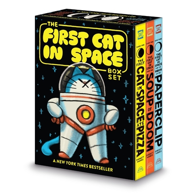
The First Cat in Space 3-Book Box Set: A Graphic Novel Collection: The First Cat in Space Ate Pizza, The First Cat in Space and the Soup of Doom, The First Cat in Space and the Wrath of the Paperclip
Multiple copy pack